In 2000, the emerging optical add/drop multiplexing (OADM) technology ushered era of optical exchange. However, it could only accomplish the one-way up and down wavelength of optical network nodes.
Around 2008, the replaceable OADM (ROADM) technology appeared, enabling the optical layer to have the function of all-connected exchange. Its main structure is a multi-dimensional ROADM (MD-ROADM) based on multiple 1XN selective switching (WSS) units, according to the different implementation modes of optical switching nodes in local upper and lower wavelength. ROADM went through three generations, and it succesffully made the switching function more and more complete and the networking more and more flexible. The development history of all-optical exchange is shown in Figure 1 below.

Figure 1 development history of all-optical exchange
The 1st generation of ROADM is a directionless redistributable OADM (Directionless ROADM), which introduced the WSS technology on the line side, realized the mesh light exchange on the line side, but the OADM combination/wave divider (Mux/Demux) structure on the sideline is remained, as it can only support the single-direction up and down signals.
The 2nd generation of ROADM is a colorless directionless ROADM (CD-ROADM). The model uses two 1×N type WSS devices to replace the Mux/Demux used by the D-ROADM on the backside, realizing the colorless, directionless, up and down wavelength exchange. But there is only singular up and down channel, and the channel will be blocked when there are multiple wavelengths need to be switched up and down.
The 3rd generation of ROADM is a colorless direction-less contentionless ROADM (CDC-ROADM). Its core technology is to solve the obstruction of upper and lower wave of the second generation CD-ROADM. CDC - ROADM added multi - cast switch (MCS) technology in the roadside, which eventually made ports and branches all connected and realized the full wavelength switching function, meeting the colorless, no direction, no obstruction of free up and down.
All ROADM technologies mentioned above have disadvantages such as limited switching dimension, complex fiber connection, difficult operation and maintenance, poor reliability, and high power consumption. With the development of optical network technology, the next generation of the technology of fiber optic switch, on the basis of meeting the basic functions of existing CDC-RODAM, will develop to larger dimension, higher integration, lower power consumption and simplified operation and maintenance. As a result, OXC (Optical Cross Connection) technology come to our sight.
Optical cross-connect (OXC) switch is a kind of N * N matrix optical switch which can be built with 1 * N optical switches, as shown in figure 2, in order to build a N * N OXC module, 2N 1 * N optical switches will be needed. As the port number N increase, the size and the cost of the OXC module increase dramatically, so the port number is usually limited to 32 x 32.
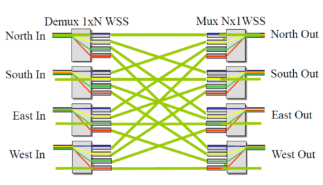
Figure 2 4×4 OXC module built with 8 1×4 switches
The second technical solution for OXC implementation is cross-bar optical switches based on MEMS micromirror arrays. The first matrix optical switch based on 2D MEMS technology was reported by L.Y. Lin et al of AT&T Laboratory in 1998, as shown in Figure 3, in order to realize n-by-n port optical switch, an N-by-n scale micromirror array is needed. All the optical paths of this kind of MEMS optical switch are in a plane, which is why it is called a 2D MEMS optical switch.
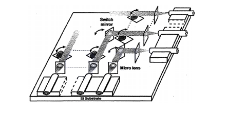
Figure 3. The first 2D MEMS matrix switch
Li Fan from OMM reported another MEMS micro-mirror array for matrix switches in 2002,

Figure 4. The 2D MEMS micro-mirror array reported in 2002
Matrix optical switches based on 2D MEMS micro-mirror array have the advantages of simple structure and easy to encapsulate, but its scalability is limited, normally the maximum port number of 2D MEMS optical switches is limited to 32×32. In the 2D MEMS optical switch, a 1D collimator array is used.
To further expand the number of OXC ports, 3D MEMS optical switches were developed. As shown in figure 5, 3D MEMS includes two MEMS micro lens array and two-dimensional collimator array. Each input fiber of collimator corresponds to one of the 1st MEMS mirror, and each output fiber of the collimator array corresponds to the 2nd MEMS micro mirror. All the micro mirror on the MEMS chips can be two axis deflection, as shown in figure 6.
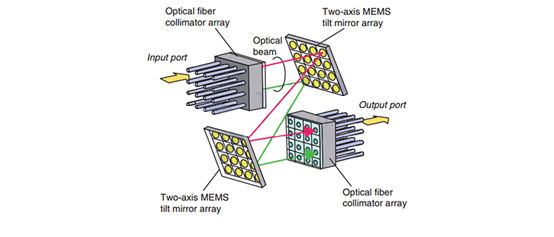
Figure 5. Basic structure of 3D MEMS OXC
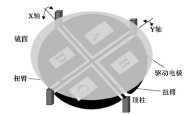
Figure 6 Two-axis MEMS tilt mirror array
Figure 7 is another 3D MEMS OXC developed by Bell LABS. It consists of two MEMS micro-mirror arrays, two 2D fiber arrays and a Fourier lens. Each input-output link is constructed by a micro-mirror on the first MEMS chip and another micro-mirror on the second MEMS chip.
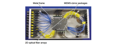
Figure 7. 3D MEMS OXC from Bell Labs

Figure 8. 3D MEMS OXC
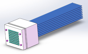
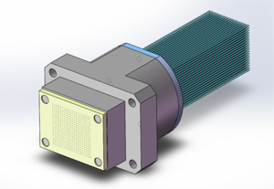
Figure 9. 2D fiber array and 2D collimator array from MEISU
Two-dimensional fiber array or two-dimensional collimator array is used in all kinds of 3D MEMS optical switches,.
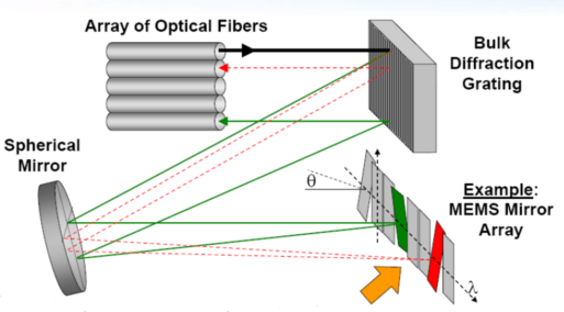
Figure 10 WSS based on MEMS technology
Thanks to the development of WSS switches based on Liquid Crystal on Silicon (LCoS), CDC-ROADM is able to evolve into the OXC. Therefore, the switching dimension and the upper and lower wave ports are multiplied on the whole equipment.
LCoS technology is used to control the refractive index of silicon-based liquid crystals through voltage, and then control the reflected phase of the incident light wavelength, so as to achieve the direction deflection of light rays, as shown in figure 12.
![]()
Figure 11 WSS based on Silicon Liquid Crystal (LCoS) Technology

Figure 12 LCoS technology
MEISU has developed 1D and 2D optical fiber array and collimator array for various optical selective switches. All the arrays of MEISU's WSS wavelength selective switch can be customized according to customers' requirements.
PICs From http://www.53179.net/a/yule/364.html